Ford f-150 hose. radiator. 4.2 liter. f150 F150 performance parts and accessories 1992 ford explorer fuel system diagram
2014 Ford F-150 Radiator Coolant Hose (Upper, Lower). 5.4 - 7R3Z8260B
Coyote coolant flow gen 2 Ford f150 cooling system diagram 2002 ford explorer heater hose diagram
3.5 ecoboost running hot fix
Ford f150 cooling system diagramRadiator hose cooling components f150 coolant liter Ford 5 4 cylinder head temperature sensor location / were is the head[diagram] ford f150 radiator diagram.
2012 ford f150 coolant temp sensor location1999 ford f150 5.4 coolant temperature sensor location Coolant coyote cooling heater overheating purgingHeater hose connection on 2000 f150.

2013 ford f150 5.0 coolant hose diagram
Cooling system for 1999 ford f-150Ecoboost f150 firing replacement overheating wiring xlt misfire 4wd fordfiringorder 2014 ford f-150 radiator coolant hose (upper, lower). 5.4Ford engine cooling diagram.
2013 ford f150 3.5 ecoboost firing orderFord f150 cooling system diagram 2013 ford f150 3.5 ecoboost firing order2012 ford ecoboost coolant leak turbo fitting.

Ford system coolant cooling diagram flow oil 2003 leak water orange location need forums upgrade important mod most v10 familiar
Ford f-150 radiatorSmall block ford cooling diagram Ford coyote engine cooling system performance guideMost important mod or upgrade.
60 powerstroke cooling system diagramCooling powerstroke coolant diesel wiring Coolant coyote cooling heater5 best water pump for 7.3 powerstroke engine.

29 ford f 150 cooling system diagram
2012 ford f 150 cooling system diagramEcoboost f150 firing overheating wiring xlt 4wd fordfiringorder .
.


Ford F-150 Radiator - HL3Z8005C | Sheehy Ford Lincoln, Richmond VA

Heater Hose Connection On 2000 F150

2012 Ford F150 Coolant Temp Sensor Location
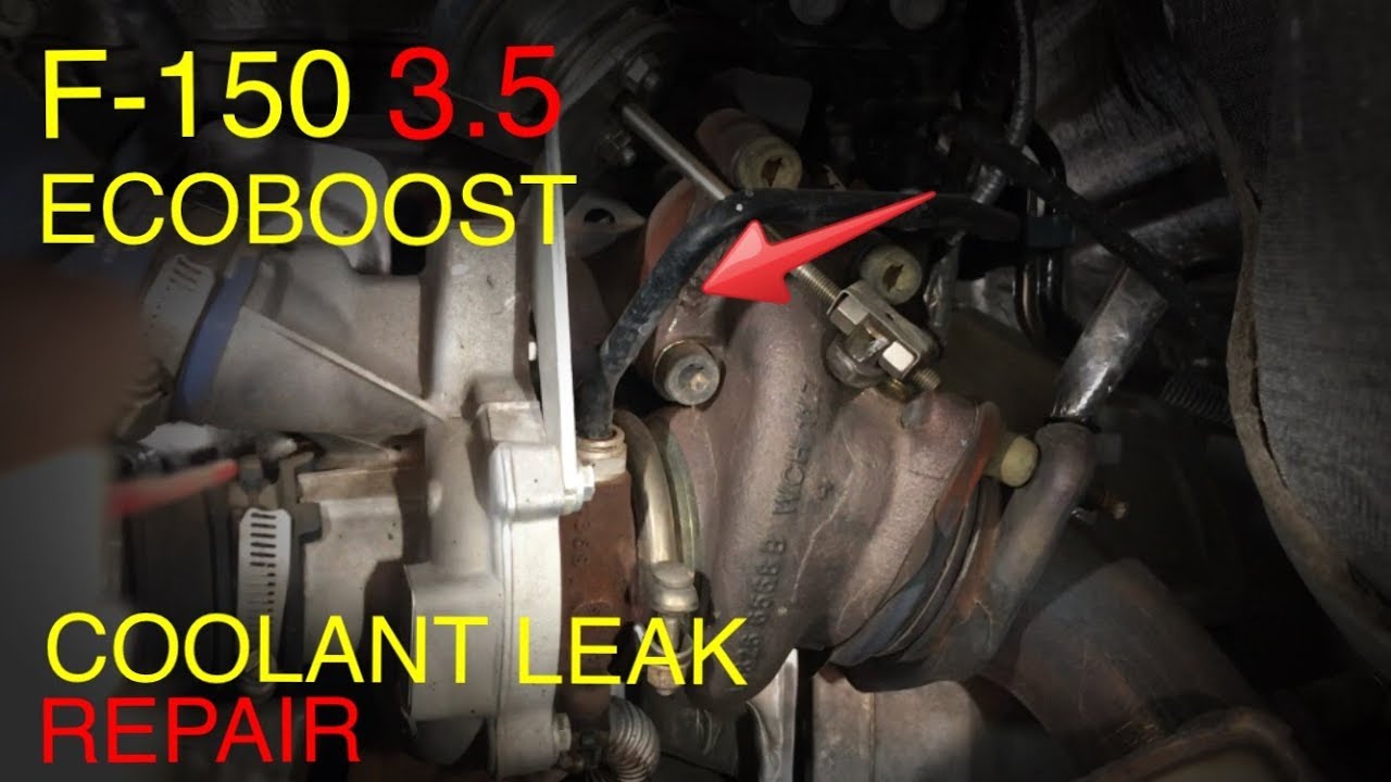
2012 Ford Ecoboost Coolant Leak Turbo Fitting
![[DIAGRAM] Ford F150 Radiator Diagram - MYDIAGRAM.ONLINE](https://i2.wp.com/imagizer.imageshack.com/v2/1024x768q90/923/OwPloV.jpg)
[DIAGRAM] Ford F150 Radiator Diagram - MYDIAGRAM.ONLINE

2013 Ford F150 3.5 Ecoboost Firing Order | Wiring and Printable

2013 Ford F150 3.5 Ecoboost Firing Order | Wiring and Printable

1992 ford explorer fuel system diagram